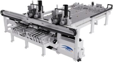
Our MODUL TT2 is a truly exceptional machine integrating within itself the functions typically carried out by two machines in series.
Roller-conveyor 6000 x 2500 - h 950 mm with freewheel rollers, divided into 3 sections for feeding the cross-cut saw. A double set of side aligners upstream of the cutting area ensures that the bars remain aligned against the right and left wooden guides.
The pusher unit consists of a robust tubular crossbeam equipped with a series of suction cups for clamping and positioning panels during processing.
The crossbeam moves on two parallel aluminum-profile shoulders fitted with steel guides, using tempered steel rollers.
The pusher’s position is electronically controlled. Position detection is performed via an encoder directly mounted on the motor. This device offers exceptional precision (reading resolution of 2/100 mm), effectively eliminating errors caused by backlash between the pinion and rack teeth.The pusher is driven by a brushless motor. The digital control of the brushless motor allows for continuous speed adjustment from 0 to 160 m/min.
The unit consists of a robust bridge structure made of normalized steel following welding. Mounted on this structure, positioned above the work surface, are the tool-holding carriages. The carriages move along high-precision hardened guides, ensuring perfect repeatability of movements and long-term durability.
Each tool-holding carriage is equipped with a precision-guided slider that allows vertical movement of two blade assemblies, which can be engaged individually via electro-actuators driven by brushless motor. This enables cutting in both directions, thereby increasing production efficiency. Additionally, by interpolating the tools (blade scorer), chipping of the edges of pre-edged or post-formed panels during cutting is prevented.
Each carriage is equipped with an upper hood designed to capture dust generated during cutting. This hood remains fixed in the working position, adjusted to the thickness being processed, to prevent delays in the work cycle. During cutting operations, the panel is secured to the machine surface by an electric pressure beam, which is coated with a scratch-resistant material. This coating also prevents the compression of wood particles onto the panel's surface.
The cutting table features vertical movement; by lowering during the panel's transit phases, it prevents scratching of the laminated bars. Motorized belts are positioned on the cutting table, both before and after the blade path, to facilitate the movement of the bars.
The discharge of the front trim is achieved by pushing it forward through the bar's advancement, while the rear trim is discharged via a tilting hatch integrated into the worktable.
Additional extraction points, located beneath the worktable and at the end of the cutting line, are designed to capture dust that escapes the upper hood's collection system.
A double set of motorized side aligners, located downstream of the cutting area, ensures that the bars remain aligned against the right and left wooden guides to maintain the orthogonality of the produced pieces.
A movable pneumatic extractor, positioned on the work surface, allows for the discharge of rear trims up to a maximum of 50 mm; for larger trims, discharge must be performed at the front.
The outfeed table of the machine features a tilting mechanism for evacuating front trims. It consists of a 600 mm long tubular structure equipped with 12 transport and positioning belts. The belts are toothed and laterally guided, constructed with internal steel filaments and rubber coating, ensuring proper grip on the panel during transport.