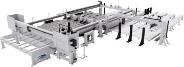
MODUL TL + ROT2 falls under our "CUSTOM MADE" machines.
At the customer's specific request, we successfully developed this longitudinal panel saw, which not only performs cutting in both directions but also has the capability to rotate the panel by 90°.
This unique feature eliminates a task previously handled by the operator, making it automated, significantly more precise, and efficient.
Each blade is equipped with an independent motor, allowing for bidirectional cutting, which increases productivity and prevents chipping on the edges of pre-edged panels during cutting. The stroke of the cutting units is controlled by two actuators managed by two brushless motors with their respective drivers.
The loading area consists of a motorized roller-conveyor with front loading, integrated into the lifting table platform for panels measuring 4500 x 2200 mm. The rollers are mounted on the platform through dedicated supports welded to the lifting table itself. Each roller is equipped with a toothed sprocket on one end and is motorized via a gear motor and chain system.
The lifting table uses electronically controlled screws and does not require a pit. The use of worm screws for table elevation ensures precise adjustments, uniform movement, and enhanced safety against accidental drops. The lifting mechanism operates with a rotating screw system, reducing maintenance costs. The screws feature a toothed sprocket on one end and are motorized via a gear motor and chain system, integrated into the table frame.
The pusher unit consists of a robust tubular crossbeam fitted with four pushing arms for loading and aligning the selected stack. The crossbeam moves along two parallel supports equipped with hardened steel rollers and guides. The dual-T structure of the supports ensures high rigidity. The pusher's position is detected via an encoder mounted on the motor.
The loading table is equipped with two panel alignment devices. These consist of two motorized movable crossbeams: the rip aligner is located beneath the table, while the cross aligner is positioned above. Their function is to align the stack against fixed references on the table surface.
The cutting center consists of a single steel-structured platform coated with special anti-scratch bristles. At its center, there is a rotary table designed to accommodate the entire stack of panels. The rotary table also integrates lateral and frontal aligners.
The central pivot and specific external guides enable the rotary table, driven by an inverter, to execute a programmed 90° rotation. This allows for precise orientation of the panel stack and facilitates cutting in various configurations.
The position of the pusher is detected by means of an encoder mounted on the motor. This device is extremely precise) and is not affected by any errors due to the play between the pinion teeth and those of the rack. The pusher is driven by a brushless motor. The digital drive of the brushless motor allows the continuous adjustment of the pusher speed from 0 to 50 m/min.
The pusher unit consists of a robust tubular crossbeam equipped with two clamps for securing and positioning panels during processing. The crossbeam moves on hardened steel rollers along two parallel supports, which are also fitted with steel guides. The dual-T structure of the supports ensures high rigidity.
The pusher's positioning is electronically controlled. The pusher's position is detected via an encoder mounted on the motor. This device offers exceptional precision and is not affected by potential errors caused by backlash between the pinion and rack teeth. The pusher is powered by a brushless motor. The digital control of the brushless motor enables continuous speed adjustment, ranging from 0 to 50 m/min.
The unit consists of a robust bridge structure made of steel, normalized after welding. This structure, positioned above the worktable, houses the tools carriage. The carriage moves along high-precision, hardened guides, ensuring perfect repeatability of movements and long-lasting durability. Mounted on the tool carriage is a column with precision guides, along which two blade-holding motors slide vertically. Each motor can be individually engaged.